
PIPING STRESS ANALYSIS A BIT DYNAMIC…
Objective
The objective of pipe stress analysis is to ensure safety against failure of the Piping System by verifying the structural integrity against the loading conditions, both external and internal, expected to occur during the lifetime of the system in the plant. This is to be undertaken with the most economic considerations.
*Ensure that the stresses in the piping components in the system are within the allowable limits.
* Solve dynamic problems developed due to mechanical vibration, acoustic vibration, fluid hammer, pulsation, relief valves etc.
* Solve the problems associated due to higher or lower operating temperature such as:
b) Nozzle loading on the connected equipment
c) Pipe displacements
d) Loads and moments on the supporting structures.
The steps involved in the stress analysis can be listed as . .
* Identify the potential loads that the piping system would encounter during the life of the plant.
* Relate each of these loads to the stresses and strains developed.
* Get the cumulative effect of the potential loads in the system.
* Decide the allowable limits.The system can withstand without failure.
* After the system is designed, to ensure that the stresses are within the safe limits.
Types of loads
All the American code for Pressure Piping classify the loads mainly into three types . .
* Sustained Loads: Those due to forces present during normal operation
* Occasional Loads: Those present during rare intervals of operations
* Displacement Loads: Those due to displacement of pipe
LOADS ON PIPING
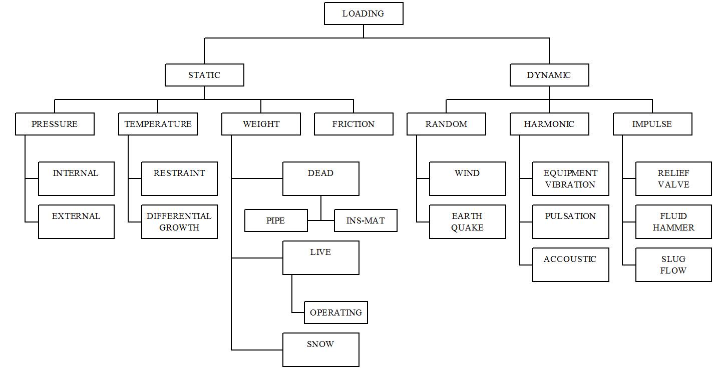
Double click over picture for clear view
PURPOSE OF DYNAMIC ANALYSIS
- Dynamic analysis is required whenever there is any dynamic load acting on piping system.
- Dynamic loads are those which changes quickly with time like earthquake, fluid hammer, vibration, relief valve etc. As a result, piping system may not have time to fully react to the applied load before it changes & system become unbalanced i.e. sum of forces & moments on system are not zero. Due to these unbalanced forces, piping system moves according to
F= M*A
These induced system reaction are not equal to applied loads & may be much higher or much lower.
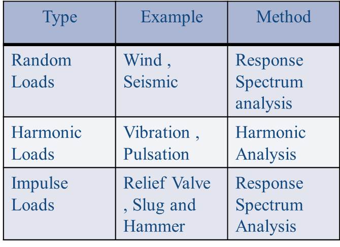
TYPES OF DYNAMIC ANALYSIS
- There are different types of dynamic loads acting :
- Model Analysis is used for Natural Frequency Check.
EARTHQUAKE / SEISMIC RESPONSE SPECTRUM ANALYSIS
Ground motion associated with seismic event is supplied as displacement, velocity or acceleration response spectra. The assumption is that all the supports move with the defined ground motion & the piping system “catches up” to the support, it is this inertia effect which loads the system.
- Input data required for Seismic response spectrum analysis are:
- Suggested Damping (in % of critical) values: 2%, 2.5% or 3.5%..
- Cut-off frequency
- Site spectrum: generally Time period v/s Acceleration or Frequency v/s Acceleration spectra (see table 1).
- Different Steps involved in Seismic response spectrum analysis inputting:
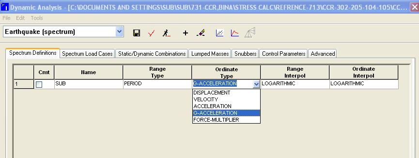
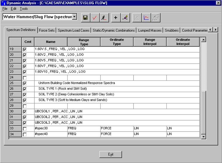
Spectrum Definition:
Earthquake loads are defined by defining one or more response spectra & applying them in a specified direction over part or all of the piping system.
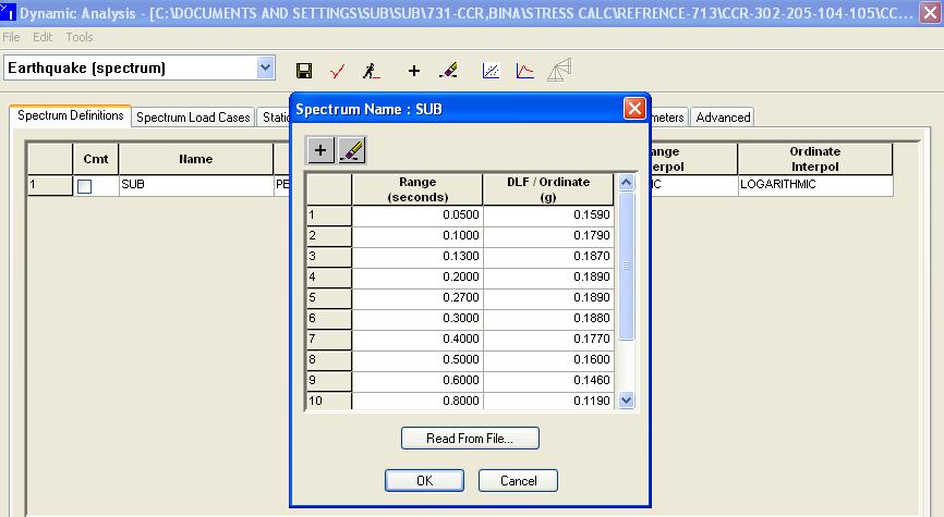
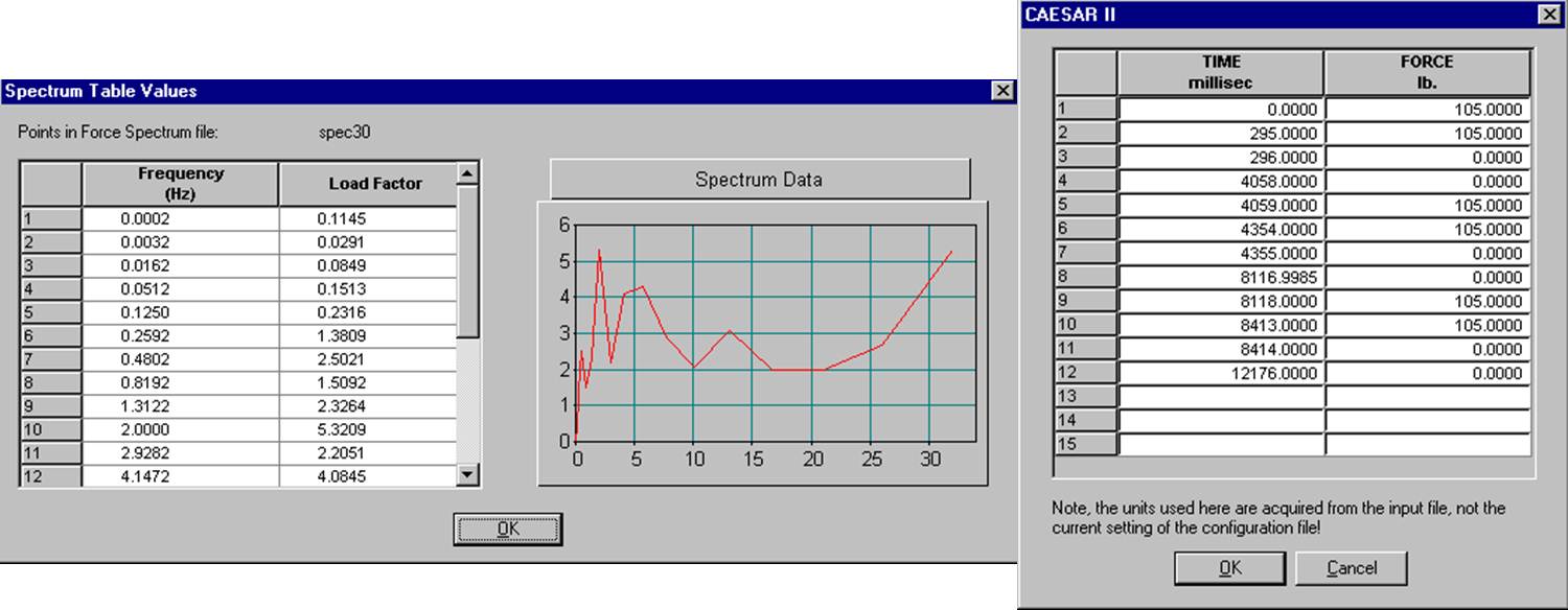
2. Generate Response Spectrum Table: Response spectrum table values can be entered directly or built & stored as a file for use by CAESAR II. It must first be defined in the Spectrum Definition page.
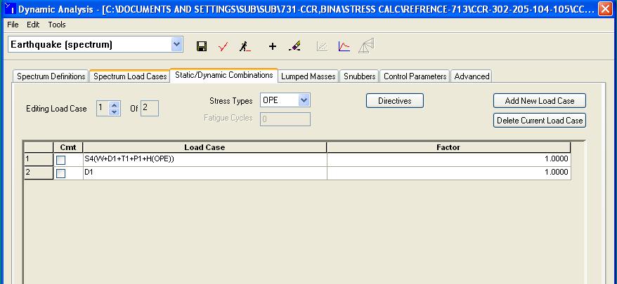
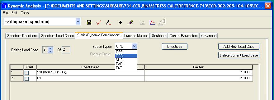
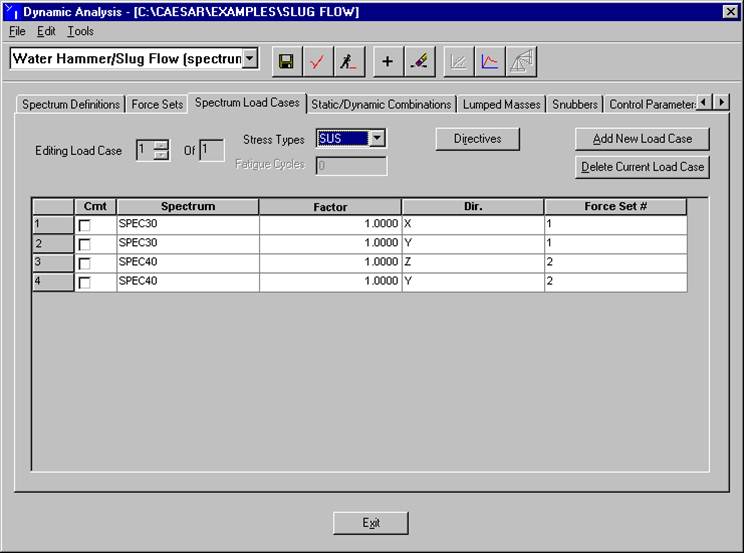
3. Spectrum Load Cases: Load case consist of simultaneously applied spectra. Each spectrum in the shock case is assigned a direction & factor. The factor is used to modify the magnitude of the shock.

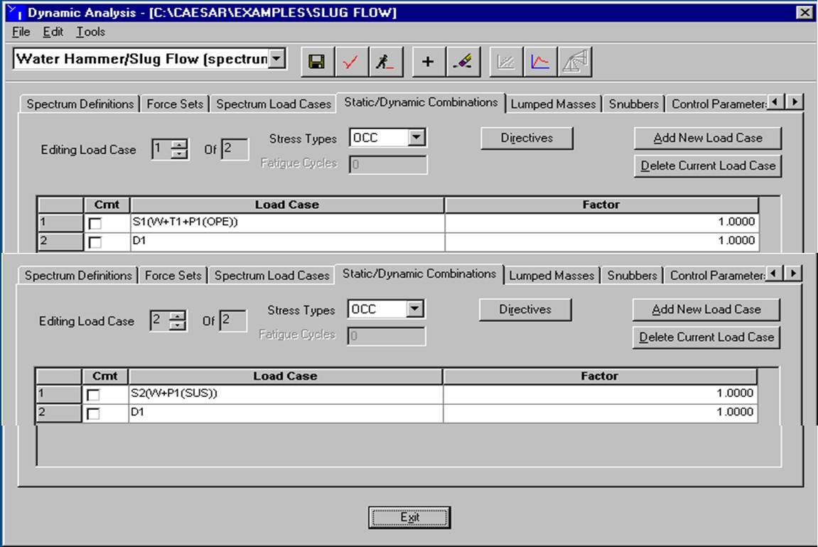
4. Static / dynamic Combination: Each shock case produces an output report listing disp., forces, moments & stresses. The sum of sustained & occasional stresses is compared to the occasional allowable stresses and operating case is combined with dynamic case to check the nozzle loads and restraint loads. This combination is provided through the Static / Dynamic combination page.
EARTHQUAKE / SEISMIC(RESPONSE SPECTRUM) ANALYSIS
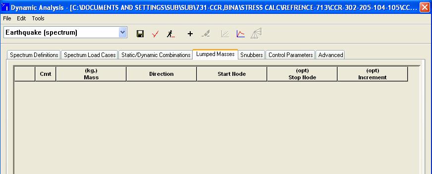
Lumped masses & Snubbers: If there are any lumped masses in piping system then we have to enter that in dynamic inputting otherwise left blank.
Also if we require snubbers in our piping system then they must be entered in dynamic inputting otherwise left blank.
6. Control Parameters: These parameters describe how the analysis will be conducted.
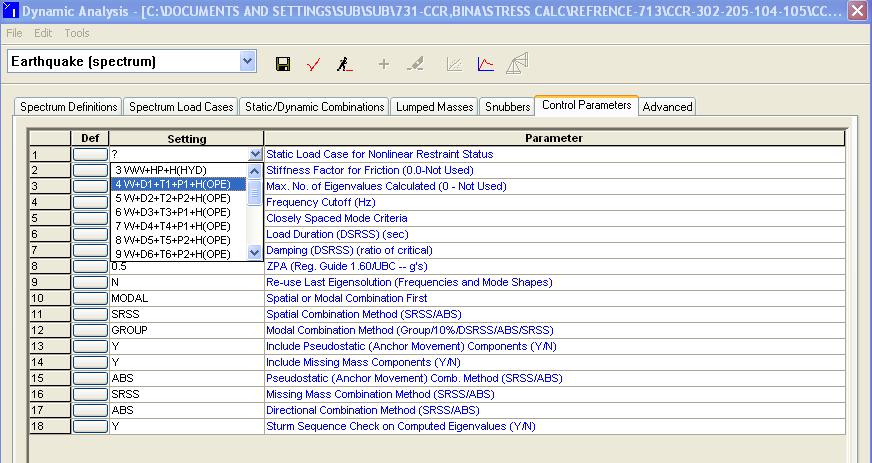
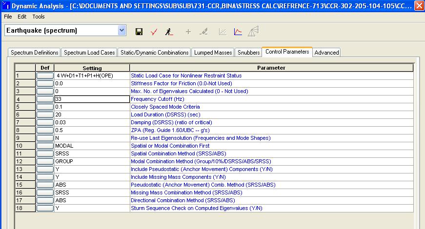
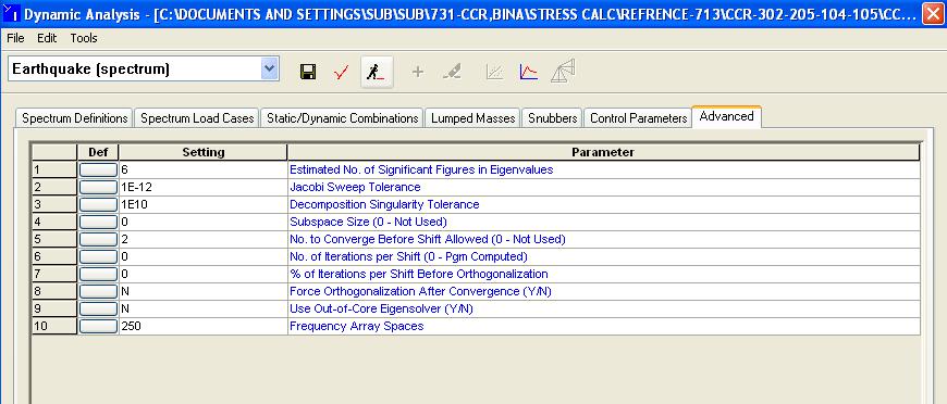
7. Advanced Parameters: These parameters are rarely to be changed by the user.
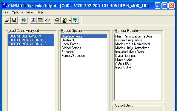
DYNAMIC OUTPUT: Different things to be checked in Dynamic Output includes:
Natural frequencies & Modes mass normalised: In this we check whether our natural freq. is more than the Cut-off frequency or not. If not then we have to take the corrective measures.
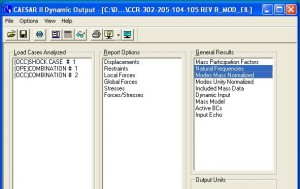
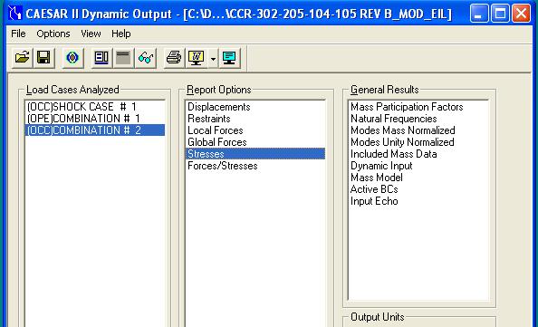
2. Stresses: In this we will compare the sum of sustained & occasional stresses with the occasional allowable stresses .
3. Restraint summary: In this we will check the nozzle loads and restraint loads in operating and sustained plus occasional case .
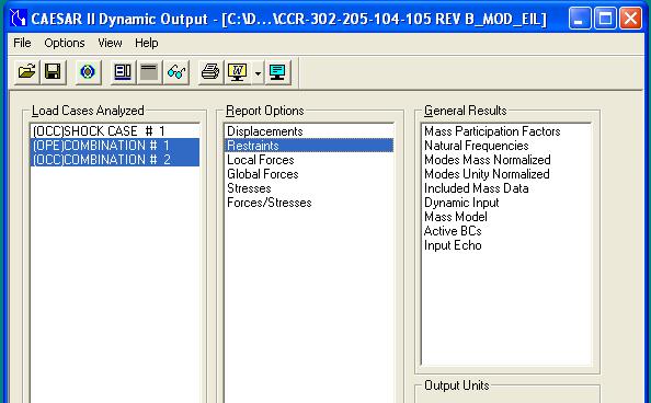
4. Displacement summary: In this we will check the system’s displacement in shock, operating and sustained plus occasional case .
SLUGE FLOW/WATER HAMMER RESPONSE SPECTRUM ANALYSIS
Slug Flow Calculation
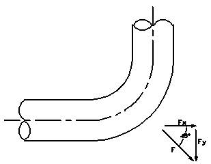
Should a slug for condition be considered, the forces on an elbow may be determined as follows:
The static force on a bend due to steady fluid flow is
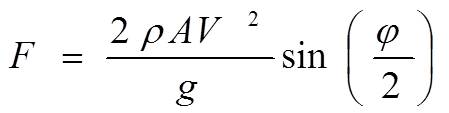
For a 90° Elbow (φ = 90),
where ρ = density of the liquid (lb/ft³)
V = Velocity of vapor (ft/sec)
A = Area of cross-section (ft²)
g = gravitational constant (32.2 ft/sec²)
The Stresses and forces caused by the impact of slug will be 1.5 – 2.0 times the static force.
Considering DLF = 1.5 for impact loading ,
Restraint Application
Restraints designed for slug flow will allow movement due to normal operation conditions; however the design will be primarily for excessive movement due to impact the slug. All changes of pipe run direction will require restraint e.g. the loop shall be restrained as shown. In case of any negative effect of the restraint in thermal case, sufficient gap may be introduced.
Standard guides and anchors are normally inadequate for restraining slug flow. Special design is required.
Free standing structural “T” supports are also inadequate for restraining slug flow. These supports are usually quite tall and tend to offer little resistance to horizontal loads. Consequently, even though they are not overstresses from the effects of the load, they do not sufficiently dampen the impact and the resultant displacement of the pipe at the restraint point can be a serious problem.
Slug Flow Analysis – Static Method (using CAESAR II)
Input Procedure
In the absence of process parameters, it is preferable to use the density of vapor for stress calculation as well as to find out the minimum frequency of the system. However, the hydrostatic load may be used for the design of supports. This is applicable wherein hanger selection is not required. Systems which have hanger design requirement, it is advisable to refer all relevant process data and find out the equivalent density of the fluid which is more realistic approach
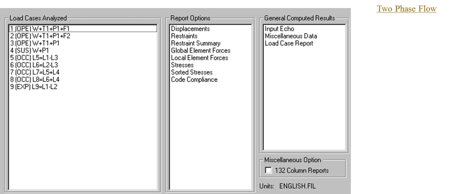
Load Cases to be built up
Slug Flow Analysis – Response Spectra Method (Dynamic analysis using CAESAR II
Normally, Slug force is treated as an impulsive force. This method is based on the assumption that the slug traverses the elbow and then suddenly drops to zero again. It is also assumed that the slug is formed across the pipe full cross section. The duration of slug is calculated based on the length of slug and stream velocity. This results in short duration impulsive loads on the pipe.
The slug size is calculated based on the length of the pipe before the elbow & liquid volume fraction i.e. Length of liquid slug = Length of pipe * Liquid volume fraction
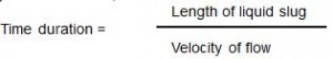
Duration of slug is calculated as,
The slug periodicity is calculated as,

Force on the elbow due to fluid flow is calculated as,
Faxial = ρ V² A (1- cosθ )
Forthogonal = ρ V² A sinθ
Where
Faxial Force on elbow in axial direction ( N )
Forthogonal Force on elbow in orthogonal direction ( N )
ρ Density of liquid ( Kg/ m³ )
A Internal cross-sectional area of pipe in ( m²)
V Stream velocity ( m/Sec )
θ Angle of bend ( Degree )
It is assumed that the elbow is subjected to force due to liquid slug and drops to a smaller value based on the density of gas, after some duration as the liquid traverses the elbow. This load is treated as a rectangular pulse load with the duration and periodicity calculated as above. The no. of cycles are given as per maximum limit of CAESAR-II package.
Natural frequencies of the piping system is calculated for the few modes up to frequency cut-off of 33 Hz.
Slug Flow Analysis – Dynamic Method (using CAESAR II)
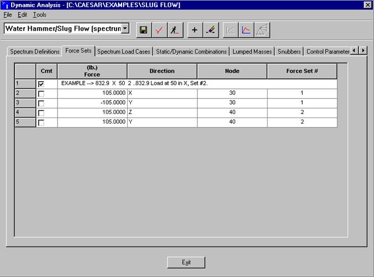
Response Spectra – Input
Organizations can compel their customers and employees to resolve disputes in arbitration proceedings bound not by state or federal law, but by religious edict.