
Some Basics of Burried Piping
Motive
Motive of this document is to explain the basic principles of evaluation the stresses generated in underground piping and to understand the stiffnesses associated therein.
Expansion stresses
Assume that the pipe is sufficiently long for the friction between the pipe and the soil to fully restrain the pipe, the maximum compressive thermal stress in this kind of a fully restrained pipe can be calculated by
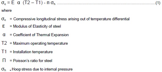
The axial force Fa in this pipe or at an anchor due to the temperature difference is only a product of this expansion stress and the area of cross section of the pipe.
However, because of the passive soil resistance, bending moments will develop in the pipe, especially at the elbows, which is also attributed by these Axial reaction forces. This can either be calculated by a Finite element method, or can be estimated to a certain degree of accuracy by assuming closely spaced springs in order to model the stiffness/resistance of the soil in Piping stress analysis.
Figure 1, on the shows a close range modeling of the issue at hand in a Constrained Pipe expansion.
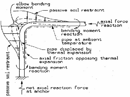
Figure 1 : Bending Moment in the underground pipe
Mathematical modeling of Soil as a spring
Soil loading on a pipe can only be modeled by discrete non-linear springs. In the following sections, we would try to evaluate the maximum soil spring forces and displacements.
Soil properties representative of the backfill should be used to compute axial soil spring characteristics.Other soil spring characteristics should generally be based on the local soil properties. Backfill soil properties can only be used for calculating the horizontal and vertical soil spring forces only when it can be shown that the extent of the pipe movement relative to the surrounding backfill soil is not influenced by the soil outside the pipe trench (assuming the existence of one).
A fundamental assumption of our calculations is that the soil force is constant once it reaches a maximum value. The dimension for the maximum soil spring force would be force per unit length of the pipe. Also, the soil is assumed to be uniform in nature throughout the area in which the pipe runs.
Axial Soil Spring
The maximum axial soil force per unit length of pipe that can be inflicted on to the pipe is
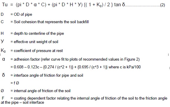
Representative values of “f” for various types of external pipe coatings can be assumed from the following table :
• Concrete coating f = 1.0
• Coal tar coating f = 0.9
• Rough steel f = 0.8
• Smooth steel f = 0.7
• Fusion bonded epoxy f = 0.6
• Polyethylene f = 0.6
The following assumptions can also be noted for normal cases, for displacements at Tu
= 3 mm for dense sand
= 5 mm for loose sand
= 8 mm for stiff clay
= 10mm for soft clay
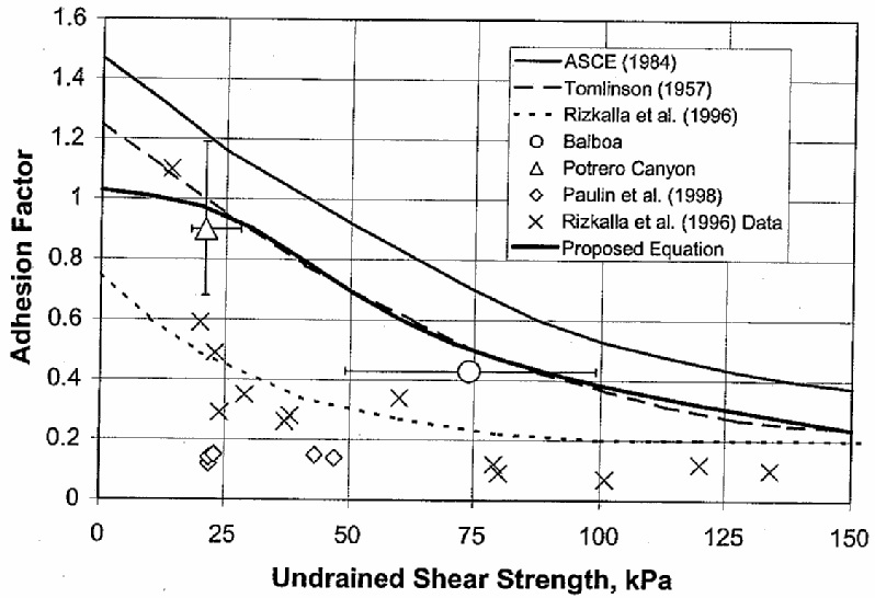
Figure 2 : Plotted values for the Adhesion factor , α
Lateral Soil Spring
The maximum lateral soil force per unit length of pipe that can be transmitted to the pipe is :
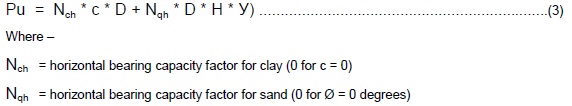
The expressions for Nch and Nqh are closed form fits to published empirical results. Please refer
Figure 3 for the plot values.
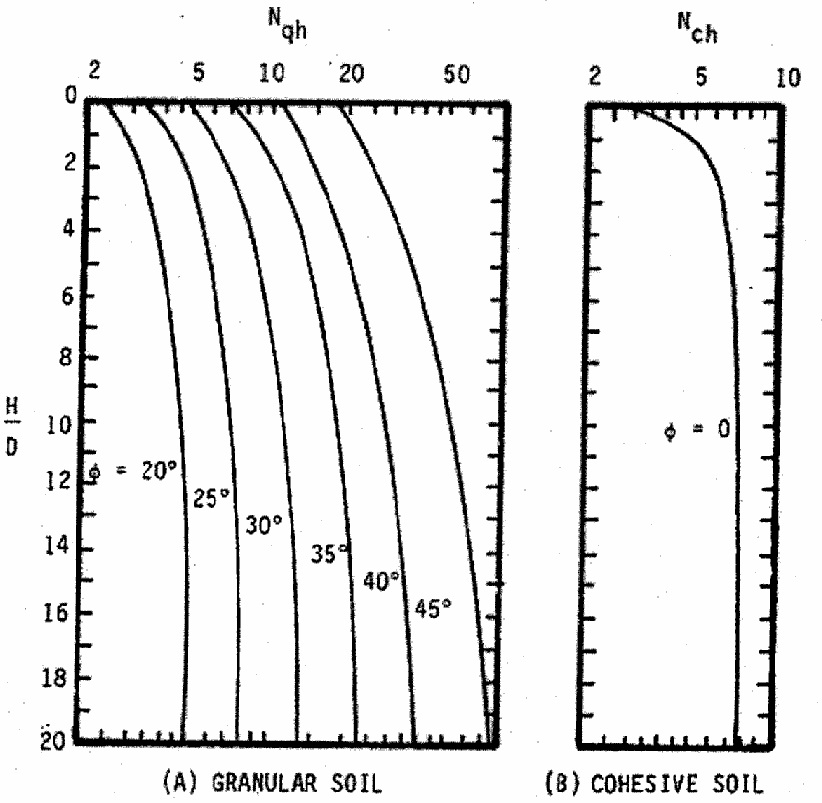
Figure 3 : Values of Nch and Nqh
Mathematically, these values can be represented as follows :
![]()
Nqh can be interpolated for intermediate values of Ø between 20 and 45 degrees from Table 1
(refer next page).
Also to be noted is that the displacement at Pu can be governed by the following equation :
= 0.04 (H + D/2) < = 0.10 D to 0.15D…………………………………………………………………(6)
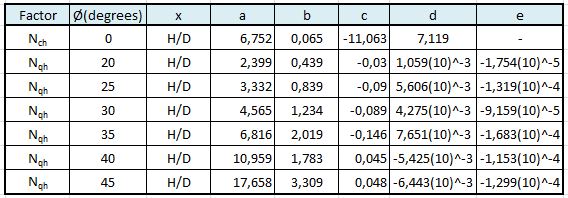
Table 1 : How to plot the values of Nch and Nqh
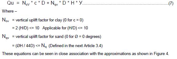
Vertical Uplifting Soil Spring
The applicability of these equations would be for relatively shallow burial depths as expressed in
the ratio of the depth of the pipe centerline with that of the pipe diameter ie. H/D.
The displacement at Qu
= 0.01H to 0.02H for dense to loose sand < 0.1D
= 0.1H to 0.2H for stiff to soft clay < 0.2D
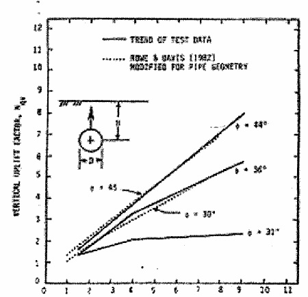
(H/D)
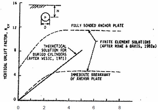
Figure 4 : Ranges for Nqv and Ncv
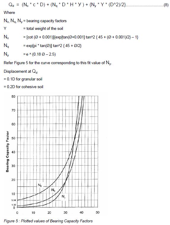
Vertical Bearing Soil Spring
Reference:
For more detail refer Guidelines for the Design of Buried Steel Pipe, ASCE, American Lifelines Alliance
A guided wave is generated that travels some distance along the pipe. Changes in wall thickness reflect the wave. The technique can effectively survey a long run of pipe from a single location, reducing the amount of excavation necessary and helping focus work in areas known to be deficient.